Difference between revisions of "Air-to-ground radar"
m |
|||
| (2 intermediate revisions by one other user not shown) | |||
| Line 17: | Line 17: | ||
[[File:Ground_radar.jpg|border|frameless|600x600px]] | [[File:Ground_radar.jpg|border|frameless|600x600px]] | ||
| − | =Ground Map (GM)= | + | ==Ground Map (GM)== |
| − | GM mode is designed to provide a map display on the MFD suitable for navigation and for target detection. Weapons delivery is supported by a ground stabilized cursor whose position is indicated on the map display and is used to center the scan coverage. GM returns are displayed on a plan position indicator (PPI) (polar coordinates) sector format. The submodes EXP, 8:1 DBS1, and 64:1 DBS2 magnify a patch of the PPI sector resulting in increased resolution of the map and more precise cursor placement | + | GM mode is designed to provide a map display on the MFD suitable for navigation and for target detection on targets that are NOT moving. Weapons delivery is supported by a ground stabilized cursor whose position is indicated on the map display and is used to center the scan coverage. GM returns are displayed on a plan position indicator (PPI) (polar coordinates) sector format. The submodes EXP, 8:1 DBS1, and 64:1 DBS2 magnify a patch of the PPI sector resulting in increased resolution of the map and more precise cursor placement. |
| − | |||
| − | |||
STP, OA and SP cursor position are used for weapons delivery and centering of the map coverage. A STP, OA or SP can be selected as an initial cursor position. STP and OA information is used to continually determine the cursor range in all three axes from the aircraft to the STP. Therefore, the cursor is ground stabilized at that location. | STP, OA and SP cursor position are used for weapons delivery and centering of the map coverage. A STP, OA or SP can be selected as an initial cursor position. STP and OA information is used to continually determine the cursor range in all three axes from the aircraft to the STP. Therefore, the cursor is ground stabilized at that location. | ||
| Line 27: | Line 25: | ||
The cursor position is depicted relative to the map at the intersection of the horizontal and vertical lines on the MFD and is also indicated by the steerpoint diamond in the HUD. The CURSOR/ENABLE control is used to move the cursor onto the feature of interest on the displayed map. | The cursor position is depicted relative to the map at the intersection of the horizontal and vertical lines on the MFD and is also indicated by the steerpoint diamond in the HUD. The CURSOR/ENABLE control is used to move the cursor onto the feature of interest on the displayed map. | ||
| − | Pressing CZ on the MFD removes previous adjustments made to the initial A-G cursor position. This is useful if adjusting gain, changing submodes, or lowering range scale. In this case, the A-G cursor may be displaced from the correct position over the target. | + | Pressing CZ on the MFD removes previous adjustments made to the initial A-G cursor position. This is useful if adjusting gain, changing submodes, or lowering range scale. In this case, the A-G cursor may be displaced from the correct position over the target. This function will reset any delta caused by the cursor. |
| − | Scan pattern size and location in GM are controlled both automatically and manually. A 1-bar scan is roll and pitch stabilized with ±10, ±30, or ±60 azimuth scan width selections available from the MFD. | + | Scan pattern size and location in GM mode are controlled both automatically and manually. A 1-bar scan is roll and pitch stabilized with ±10, ±30, or ±60 azimuth scan width selections available from the MFD. |
Range resolution increases by 2:1 for each decrease in range scale while in the NORM, EXP and DBS1 submodes. Changing range scales in DBS2 has no effect on range resolution. | Range resolution increases by 2:1 for each decrease in range scale while in the NORM, EXP and DBS1 submodes. Changing range scales in DBS2 has no effect on range resolution. | ||
| − | + | ==Ground Moving Target (GMT)== | |
| − | + | GMT mode is designed to detect moving targets on land or sea. Moving vehicles including cars, tanks, trucks, ships, aircraft while taxiing or helicopters in flight can be detected at low speeds. A background map is available for navigation and detection of stationary targets. Normal (NORM) and expand (EXP) submodes are available along with the FZ option similar to GM. | |
| + | Acquisition to Ground Moving Target Track mode (GMTT) is available for tracking moving targets in the real APG-68; however, in BMS it is not currently modelled. Targeting pods (AN/AAQ-14 LANTIRN or AN/AAQ-33 Sniper) will allow you to acquire and track moving vehicles once detected with GMT mode. | ||
| − | =SEA= | + | ==SEA== |
SEA mode is designed to detect sea-borne targets in low sea states. SEA mode processing differs from GM in that more samples are integrated to produce the map. This requires a slightly slower scan rate to increase the integration time on sea targets. | SEA mode is designed to detect sea-borne targets in low sea states. SEA mode processing differs from GM in that more samples are integrated to produce the map. This requires a slightly slower scan rate to increase the integration time on sea targets. | ||
| Line 43: | Line 42: | ||
Control and operation of SEA mode are identical to GM except for the processing differences described above, and the lack of DBS submodes. The NORM and EXP submodes are available as well as the FZ option and transition to FTT. | Control and operation of SEA mode are identical to GM except for the processing differences described above, and the lack of DBS submodes. The NORM and EXP submodes are available as well as the FZ option and transition to FTT. | ||
| − | = | + | ==Ground Target Track== |
| − | + | In GM, SEA, and GMT modes, if a target is being tracked, the target will appear as a solid diamond at the intersection of the X-Y cursor and range will be displayed in the HUD slant range window | |
| − | == | + | ==Fixed Target Track (FTT)== |
| − | + | FTT is designed to automatically maintain an accurate track of a stationary discrete target for weapon delivery. FTT is available in GM, SEA or DBS modes and is initiated with a TMS up. This action initiates an acquisition sequence where the radar searches for targets about the cursor position with greater reflected intensity than the background clutter. FTT targets can be seen visually through the HUD. For weapon delivery, an A-G TD box is positioned at the target location. It is generally preferable to acquire targets from EXP or DBS, since signal and thus image quality is increased, and it is easier to differentiate targets. | |
[[File:FTT mode.jpg|border|frameless]] | [[File:FTT mode.jpg|border|frameless]] | ||
| − | + | <br /> | |
| − | |||
| − | |||
| − | |||
| − | |||
| − | |||
| − | |||
| − | |||
| − | |||
| − | |||
| − | |||
| − | |||
| − | |||
| − | |||
| − | |||
| − | |||
| − | |||
| − | |||
| − | |||
| − | |||
| − | |||
| − | |||
| − | |||
| − | |||
| − | =Air-to-Ground Ranging (AGR)= | + | ==Air-to-Ground Ranging (AGR)== |
The AGR mode is designed to provide an accurate range to a ground point for visual A-G delivery modes (CCIP, DTOS, STRAFE, EO-VIS). The radar is automatically commanded to AGR when the appropriate A-G weapon submode is selected (unless STBY or OVRD is selected). | The AGR mode is designed to provide an accurate range to a ground point for visual A-G delivery modes (CCIP, DTOS, STRAFE, EO-VIS). The radar is automatically commanded to AGR when the appropriate A-G weapon submode is selected (unless STBY or OVRD is selected). | ||
Latest revision as of 08:47, 12 January 2023
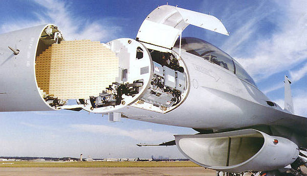
F16 is equipped with a AN/APG-68 Radar System giving it both air to air and air to ground capabilities. Within the aircraft systems, the AN/APG-68 is referred to as the Fire Control Radar (FCR)
Contents
Learning objectives
- Know the different ground radar modes (GM - GMT - SEA etc)
- Understand what is the Doppler Beam Sharpening (DBS) and it's differences with the Expanded Field of View (FOV)
- Understand the difference between STP and SP modes
- Understand the concept of the SPI and the Cursor Zero command (CZ)
- Know the symbology of the FCR page and the associated cues in the HUD
- Know the useful functions of the HOTAS about the FCR (pinky switch, TMS Up, TMS Down, etc)
Ground Radar Modes
The radar provides A-G modes for the ground map, target detection, tracking, and air-to-ground ranging. The modes are GM, SEA, FTT, GMT, AGR, and BCN (not implemented).
All modes, except air-to-ground ranging, are used to locate preplanned targets presenting a radar return. The ground map video may be expanded, frozen, or have Doppler Beam Sharpening (DBS) applied as aids in positioning the radar cursor over the target. Fixed targets may be acquired and tracked in the GM and SEA modes. The GM mode provides accurate cursor placement on conventional GM video for stationary targets. The GMT mode provides detection of moving ground targets. The SEA mode provides sea clutter reduction in moderate sea states for direct and offset sighting options and fixed target track. The AGR mode provides automatic ranging data for determining height above the target.

Ground Map (GM)
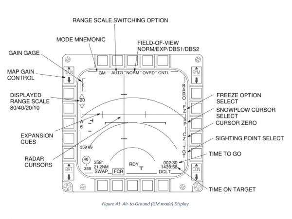
GM mode is designed to provide a map display on the MFD suitable for navigation and for target detection on targets that are NOT moving. Weapons delivery is supported by a ground stabilized cursor whose position is indicated on the map display and is used to center the scan coverage. GM returns are displayed on a plan position indicator (PPI) (polar coordinates) sector format. The submodes EXP, 8:1 DBS1, and 64:1 DBS2 magnify a patch of the PPI sector resulting in increased resolution of the map and more precise cursor placement.
STP, OA and SP cursor position are used for weapons delivery and centering of the map coverage. A STP, OA or SP can be selected as an initial cursor position. STP and OA information is used to continually determine the cursor range in all three axes from the aircraft to the STP. Therefore, the cursor is ground stabilized at that location. SP allows observation of the map area in front of the aircraft without having to constantly select steerpoints located ahead of the aircraft. Pressing TMS up creates a pseudo-steerpoint at the current cursor position. At this time, the cursor position is ground stabilized, similar to selecting a steerpoint for the initial cursor position, and cursor placement may be adjusted.
The cursor position is depicted relative to the map at the intersection of the horizontal and vertical lines on the MFD and is also indicated by the steerpoint diamond in the HUD. The CURSOR/ENABLE control is used to move the cursor onto the feature of interest on the displayed map.
Pressing CZ on the MFD removes previous adjustments made to the initial A-G cursor position. This is useful if adjusting gain, changing submodes, or lowering range scale. In this case, the A-G cursor may be displaced from the correct position over the target. This function will reset any delta caused by the cursor.
Scan pattern size and location in GM mode are controlled both automatically and manually. A 1-bar scan is roll and pitch stabilized with ±10, ±30, or ±60 azimuth scan width selections available from the MFD.
Range resolution increases by 2:1 for each decrease in range scale while in the NORM, EXP and DBS1 submodes. Changing range scales in DBS2 has no effect on range resolution.
Ground Moving Target (GMT)
GMT mode is designed to detect moving targets on land or sea. Moving vehicles including cars, tanks, trucks, ships, aircraft while taxiing or helicopters in flight can be detected at low speeds. A background map is available for navigation and detection of stationary targets. Normal (NORM) and expand (EXP) submodes are available along with the FZ option similar to GM.
Acquisition to Ground Moving Target Track mode (GMTT) is available for tracking moving targets in the real APG-68; however, in BMS it is not currently modelled. Targeting pods (AN/AAQ-14 LANTIRN or AN/AAQ-33 Sniper) will allow you to acquire and track moving vehicles once detected with GMT mode.
SEA
SEA mode is designed to detect sea-borne targets in low sea states. SEA mode processing differs from GM in that more samples are integrated to produce the map. This requires a slightly slower scan rate to increase the integration time on sea targets.
Control and operation of SEA mode are identical to GM except for the processing differences described above, and the lack of DBS submodes. The NORM and EXP submodes are available as well as the FZ option and transition to FTT.
Ground Target Track
In GM, SEA, and GMT modes, if a target is being tracked, the target will appear as a solid diamond at the intersection of the X-Y cursor and range will be displayed in the HUD slant range window
Fixed Target Track (FTT)
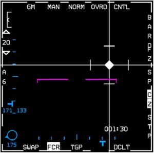
FTT is designed to automatically maintain an accurate track of a stationary discrete target for weapon delivery. FTT is available in GM, SEA or DBS modes and is initiated with a TMS up. This action initiates an acquisition sequence where the radar searches for targets about the cursor position with greater reflected intensity than the background clutter. FTT targets can be seen visually through the HUD. For weapon delivery, an A-G TD box is positioned at the target location. It is generally preferable to acquire targets from EXP or DBS, since signal and thus image quality is increased, and it is easier to differentiate targets.
Air-to-Ground Ranging (AGR)
The AGR mode is designed to provide an accurate range to a ground point for visual A-G delivery modes (CCIP, DTOS, STRAFE, EO-VIS). The radar is automatically commanded to AGR when the appropriate A-G weapon submode is selected (unless STBY or OVRD is selected).
AGR ranges to the point on the ground indicated by weapons delivery symbology in the HUD. Depending on the submode selecting AGR, the symbol in the HUD may be slewed to the desired point, or the aircraft can maneuver to place the symbol at the desired point, or a combination of both. The CURSOR/ENABLE switch on the throttle is used to slew the symbol. Different symbols (see below) are used to indicate the ranging point depending on the submode.
| Submode | Symbol | Pointing Method |
|---|---|---|
| HUD Mark | CCIP Pipper (Circle with dot) | Slew |
| Visual Air-to-Ground/Strafe/CCIP | CCIP Pipper (Circle with dot) | Manoeuvre aircraft |
| DTOS/EO-VIS | A-G TD Box (square with dot) | Manoeuvre aircraft/Slew |

