Advanced avionics
Contents
Learning objectives
- CRUS page
- Time page and ROLEX
- BINGO page
- STPT page
- MARK page
- TFR
- FLIR
DED pages
CRUS Page
The Cruise page provides information for navigation, time and fuel while cruising. It has 4 submodes: TOS, RNG, HOME and EDR
Each submode MUST BE mode selected to become active and supply accurate information and cues.(HUD carrets mainly) Remember mode-selecting is done with the M-SEL 0 button and when active highlights the area.
The submodes of the CRUS page are accessed sequentially with DCS SEQ.
TOS (TIME Over Steerpoint) submode
This submode is used a lot by flight leaders to respect mission timings.(that's what they're talking about when they're saying i.e "Lobo 1 is on carret")
When activated with M-SEL a carret is displayed on HUD in the speed tape. To ensure that you reach the steerpoint on time for TOS match your airspeed with the caret.
The ETA to the steerpoint is also displayed in the HUD.
RNG (Range) submode
When RNG is mode selected a caret is displayed on the HUD speed tape to pinpoint the best conserve fuel speed at this altitude. Optimum speed for fuel conservation changes with altitude.
Only the active steerpoint can be toggled on this subpage.
Further information given on this page shows fuel remaining when reaching the active steerpoint, wind direction and speed.
HOME submode
When HOME is mode selected 2 carets are displayed in the HUD on the speed tape and on the altitude tape. Following these 2 carets will establish the best profile to reach Home Plate (or any steerpoint designated as HMPT).
The procedure to fly this profile is to select full military power, reach the speed caret first then pitch to reach the altitude mark while maintaining the speed on the caret. Altitude may vary according to fuel burned.
Please note, optimal altitude is given in radar altitude on the DED, but may be different on your HUD scale depending on the altimeter setting. If you follow both carets you will reach the home point at the selected optimum altitude. The altitude caret will disappear once you can start your descent.
Further information displayed on this page indicates home point (can be changed to any INS steerpoint (e.g. alternate)), onboard fuel quantity remaining when reaching active steerpoint, optimum altitude for the HOME profile, wind direction and speed.
EDR (Endurance) submode
When EDR mode is mode selected a speed caret is placed on the HUD tape to give a reference speed for best endurance at this altitude. This is very useful for holding patterns or maximum endurance cruise for instance. Further information given is time to bingo, optimum Mach number and wind direction and speed.
TIME page and ROLEX
The TIME page allows the pilot to set a HACK timer and a DELTA TOS for ROLEX calls. The first line gives the current system time. The second line is the hack timer. As the arrows indicate, pressing the ICP NEXT rocker button will start/freeze/resume the timer and ICP PREVIOUS rocker button will reset the hack timer to zero. When the HACK timer is running it is also visible on the CNI page.
ROLEX calls are initiated when TOS for all steerpoints need to be adjusted. This is done through the TIME page by changing the DELTA TOS. Place the scratchpad on the DELTA TOS line and input the ROLEX value. If a minus is required start your input with the 0 (zero) ICP key for the minus sign.
- For instance: “Mamba flight Rolex +2” => TIME, DCS down to DELTA TOS: 2, 0, 0, ENTR
- Another example: “Mamba flight Rolex -3” => TIME, DCS down to DELTA TOS: 0, 3, 0, 0, ENTR
BINGO page
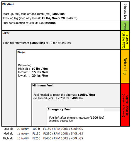
The BINGO page is where you input your briefed Joker/Bingo settings. It is made up of two lines: the first one is where you enter your Joker or Bingo setting and the second line is the total fuel remaining on board. It is good practice as a mission begins to input the Joker value. You can then reset it to the briefed Bingo value once Joker fuel is reached.
Assuming those fuel consumption :
- Low alt = 20 lbs/Nm - 100 ft to FL150 / RPM 100% / 540 kts GS
- Med alt = 15 lbs/Nm - FL150 to FL250 / RPM 100% / 540 kts GS
- Hgh alt = 10 lbs/Nm - FL250 to FL400 / RPM 100% / 400 kts GS
Here is a quick way to calculate your BINGO :
- (return leg * consumption) + (diverted leg * consumption) + normal recovery fuel (F-16 MLU ,block 10, 15, 20, 25, 30 and 32 = 1000 lbs / F-16 block 40 to 52 = 1200 lbs) + two landing trials (400 lbs).
The JOKER is usually set to BINGO + 1000 lbs which correspond to 1 mn of afterburner or 10 mn of flight time at 350 kts.
STPT page
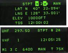
The Steerpoint page gives the pilot information about the INS steerpoint.
- The first line allows the pilots to toggle the active steerpoint with the NEXT/PREV ICP buttons (notice the up & down arrows) and the MAN or AUTO steerpoint function, which can be toggled with DCS SEQ. MAN means that the new steerpoint has to be manually selected. AUTO will increment to the next steerpoint automatically when the INS detects the proximity of the current waypoint. In AUTO mode an “A” symbol is displayed on the CNI page next to the steerpoint.
- The second line is the LATITUDE of the currently selected steerpoint. Placing the scratchpad there will let the pilot enter the latitude for this particular navigation point.
- The third line is the LONGITUDE of the selected steerpoint. It can also be changed by placing the scratchpad accordingly and entering new coordinates.
- The fourth line is the elevation of the steerpoint (the altitude at which you are supposed to overfly the steerpoint according to your INS flight plan). This is different from the real jet that has the ground spot height for steerpoint in this field (it is quite relevant to TGP mechanisation and finding the target).
- The fifth line is the TOS (Time Over Steerpoint) which gives you the local time the steerpoint will be reached, if you are following the route of flight as planned.
Setting up steerpoints
You can enter custom steerpoints using LAT/LONG coordinates entered directly in your ICP. These can be shared with wingmen over the radio in situations where data link is not enabled.
To enter a manual steerpoint:
- Press 7 (STPT) on the ICP
- Choose an unused steerpoint
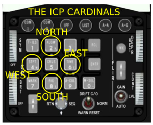
- Enter the LAT coordinate. Remember to prefix any coordinate with N or S using ICP 2 or 8.
- Enter the LNG coordinate. Remember to prefix any coordinate with E or W using ICP 4 or 5.
- Enter the elevation of the steerpoint (which is AGL I believe)
You will now be able to access a common steerpoint with other flight members.
MARK page
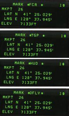
The MARK page is used to create markpoints. Ownship markpoints are stored in steerpoints 26-30.(Once #30 is filled, the next markpoint will overwrite #26 and so on)
Markpoints can be made from 4 different systems:
- OFLY (Overfly GPS/INS)
- FCR (Fire Control Radar)
- HUD (Head Up Display)
- TGP (Targeting Pod).
There are thus 4 submodes in the MARK page. To toggle between the submodes use DCS SEQ. The system defaults to a specific subpage according to master mode and Sensor of Interest (SOI) and may enable automatic markpoint recording (automatic markpoint are only made in the Air to Air mode)
Markpoints are created with TMS forward (TMS up) and are visible on the HSD page once created as a cyan cross.
Setting up mark points
To set mark points properly: Go to markpoint on ICP
- Choose sensor (e.g. TGP, HUD, FCR, etc)
- Move cursor to desired location
- TMS-Up to set markpoint
- Press 0 on ICP to jump to markpoint
To assign target steerpoints:
- Create a mark point
- Switch to steerpoint referencing the mark point
- Select HSD
- Hold Comm Switch Right to send new steerpoint
To send cursor data:
TFR (Terrain Following Radar)
It is available only on F-16s carrying both LANTIRN pods (Block 25/30/32/40 EAF/42/52+, KF-16 & F-16I). The TFR is a short range radar that allows you to follow the terrain at very low altitude with automatic fly up protection.
As with all pods / systems the TFR needs a certain amount of time to become operational. This time starts when the TFR is placed out of OFF to STBY. The TFR is ready when the NOT TIMED OUT message disappears. Obviously the chin hardpoints must be powered and the radar altimeter must be operational.
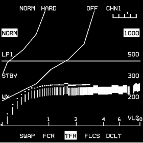
Activate the TFR by placing it in NORM and select the desired SCP. Both options highlight on the TFR page. The TFR E-scope display will start displaying a visual representation of the terrain ahead.
The TFR has 3 Ride options: HARD - SOFT - SMTH (smooth) and 7 modes of operation: OFF – BIT – STBY – NORM – LPI – WX – VLC
NORM
This is the normal mode of operation and accessed with OSB #20. It has 3 submodes:
- MAN TF: the pilot receives FPM cueing (MAN TF box) in the HUD to maintain a selected altitude above ground level. He hand flies the jet but the TFR offers automatic fly-up protection if the MANUAL TF FLYUP switch is in ENABLE. The ADV light on the MISC panel is unlit.
- AUTO TF: the flight control computer uses the vertical acceleration commands generated in the LANTIRN pod to maneuver the aircraft to maintain the selected SCP (Set Clearance Plane) altitude. In AUTO TF the ADV light on the MISC panel has the top indicator (ACTIVE) lit and a horizontal line is shown near the FPM on the HUD. The pilot can override the TFR (just like the autopilot) by depressing the paddle switch on the stick. While the paddle is depressed the STBY (bottom part of the ADV) light on the MISC panel is illuminated.
- Blended TF: the autopilot is engaged to hold a specific barometric altitude (or attitude). If the LANTIRN pod detects the aircraft violating the selected minimum AGL the system will automatically maneuver the aircraft to maintain the minimum AGL until the terrain has dropped away. A/P PITCH switch is in ALT or ATT HOLD. STBY ADV light is on. Horizontal line visible.
LPI
LPI stands for Low Probability of Intercept. It allows minimal TFR use with the RF switch placed in the QUIET position. It is activated by pressing OSB #19 or automatically upon placing the RF switch in QUIET.
NOTE: placing the RF switch in SILENT places the TFR in STBY.
WX
WX mode is used in bad weather (rain) to minimize uncommanded fly-ups due to conflicting radar returns in rain or fog. It is activated with either the MFD TFR page OSB#17 or the ICP WX button.
VLC
Very Low Clearance mode (100ft SCP) is accessed from OSB #10. This mode is to be used only on relatively flat terrain or over water.
FLIR (Forward Looking IR)
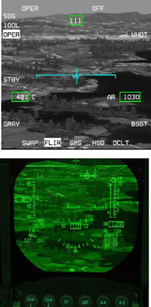
The FLIR page is only available when both LANTIRN pods are loaded on the chin pylons of compatible F-16s (Block 25/30/32/40 EAF/42/52+, KF-16 & F-16I).Obviously chin hardpoints must be powered up for the FLIR to be operational. The FLIR needs between 8 and 15 minutes to cool down before use so start the process as soon as possible. The FLIR will be ready to operate as soon as the NOT TIMED OUT message disappears from the MFD.
OSB #18 places the FLIR in standby. OSB #20 places the FLIR in operational mode (OPER). Once operational the FLIR page will display the infrared view in front of the pod.
The image can be repeated on the HUD by rotating the BRT ICP wheel upwards. The FLIR level can be changed with the ICP up and down FLIR arrows. The current gain and level values are displayed on the top left corner of the FLIR MFD.
Boresighting Procedure
OSB #10 is the boresight option. The boresight is used to better match the image in the HUD with the image from the FLIR camera at a certain range.
Depress OSB#10 and the BSGT mnemonic highlights. The HUD FLIR image can then be slewed with the cursors. Do not boresight on close objects. It is advised to boresight in flight on large objects such as the edge of a mountain or a road for instance. Once both images are superimposed correctly depress OSB#10 again and the BSGT mnemonic will return to its initial state.
Once the FLIR image is displayed on the HUD the MFD page does not need to be active, though it is advisable to have it on one of the DA buttons for easy access to boresighting.
LOOK-INTO-TURN (LIT) and SNAPLOOK capabilities
LOOK-INTO-TURN (LIT) and SNAPLOOK capabilities are available on the HUD.
- LIT: when the bank angle is above 5° holding DMS UP will shift the FLIR view slightly into the turn to provide lead obstacle clearance. The FLIR image reverts to forward looking when DMS UP is released.
- SNAPLOOK: The view can be shifted further in flight by holding DMS UP and moving the cursors in any direction, even in a turn. The view will revert to forward looking when DMS UP is released.
When LIT or SNAPLOOK are active the FPM is dashed.
{{#invoke:Navbox|navbox}}
