Difference between revisions of "Data link"
| (14 intermediate revisions by 2 users not shown) | |||
| Line 1: | Line 1: | ||
| + | [[File:BMS datalink.png||none|600px|left|]] | ||
| + | Datalink uses UHF and VHF radio to provide digital data communications with other users that have an IDM (Improved Data Modem). The IDM converts digital data to audio data for UHF or VHF radio transmission. When data is received from other users, the IDM converts the audio data to digital data and sends it to the avionics system for display in the cockpit.<br /> | ||
| + | Datalink '''must not''' be confused with the link 16. | ||
| + | |||
=Learning objectives= | =Learning objectives= | ||
| − | |||
#Understand how to pre-brief IDM | #Understand how to pre-brief IDM | ||
#Host a datalink session | #Host a datalink session | ||
| Line 7: | Line 10: | ||
#Recognize HSD symbology for datalink | #Recognize HSD symbology for datalink | ||
| − | = | + | =Learning Files= |
| − | + | Video from Krause made with BMS 4.32 | |
| − | * | + | <embedvideo service="youtube" dimensions="500">https://www.youtube.com/watch?v=XWyvJ99L2k4&</embedvideo> |
| − | * | + | |
| − | *Assign IDM in briefing like AA tacan assignments | + | =General information= |
| + | ==Introduction== | ||
| + | Datalink allows the flight lead and his wingmen increased situational awareness (SA), the ability to pass positional information about each jet in the flight to all flight members, to target flight members on to air-to-air or air-to-ground targets, to easily execute tactics that go beyond the visual arena and regain visual mutual support should a flight member become a “lost wingman”.<br /> | ||
| + | The DL system allows up to 8 IDM equipped aircraft to transmit and receive intraflight data link messages. | ||
| + | ==Modes of operations== | ||
| + | ===Demand Mode Operation=== | ||
| + | The Demand (DMD) and Assign (ASGN) data link modes allow a team member to obtain a “one-shot” team situational awareness update (an intraflight transmission round) on an “as needed” basis.<br /> | ||
| + | The DMD and ASGN modes also enable the option to make assignments to other flight members.<br /> | ||
| + | The messages transmitted allow each member to see the positions and headings of other members and their bugged target on the HSD page and FCR page<br /> | ||
| + | '''Beware :''' Both A-A Request and A-A Reply messages are snapshots in time. Reply messages are extrapolated for 8 seconds. Once this extrapolation period ends, the symbols will disappear. | ||
| + | ===Continuous Mode Operation=== | ||
| + | The Continuous (CONT) mode allows the pilot to request continuous update of request and reply intraflight messages. This is the mode that also requires coordination amongst flight members if you are flying in the multiplayer environment, as only one aircraft needs to be in CONT mode and initiates the CONT data link round. | ||
| + | ===Data Link Symbology=== | ||
| + | Air-to-air and air-to-ground data link information may be selected for display on the HSD MFD format by selecting ADLINK (OSB 16) and/or GDLINK (OSB 17) on the HSD CNTL page (both are on by default).<br /> | ||
| + | When ADLINK is selected, intraflight member’s ownship positions and the locations of their bugged targets are displayed on the HSD. This same symbology is also displayed on the FCR provided the FCR is in one of the air-to-air radar modes.<br /> | ||
| + | When GDLINK is selected, data linked steerpoint (or mark-point) and FCR air-to-ground cursor positions will be displayed on the HSD. | ||
| + | |||
| + | :*''Data Link Friendly'': Wingmen are displayed on the HSD by a half circle with a line projecting from the top of the half circle. The symbols are oriented on the HSD based on ground track. Flight member number is displayed at the top of the symbol and altitude is displayed at the bottom of the symbol. | ||
| + | :*''Data Link Unknown'': Ownship and wingmen's bugged targets are depicted as half squares with a line projecting from the top half of the half square. Flight member assignment number and target altitude are displayed at the top and bottom of the symbol, respectively. | ||
| + | :*''Data Link Targets'': Outside the HSD FOV. Data link friendly or data link unknown targets which are outside of the HSD field-of-view are indicated by an arrow pointing in the direction of the target positioned on the outer range ring of the HSD. | ||
| + | :*''Data Link Steerpoints'': Are stored in steerpoints 71-80. Ownship Markpoints are shown as a small X symbol. Data link steerpoints are shown as a large X. | ||
| + | :*''Data Link FCR A-G Cursor Position'': The data link A-G cursor position is displayed on the HSD as an asterisk with the sending flight member's number above it. | ||
| + | <gallery widths=347px heights=347px mode="packed"> | ||
| + | File:BMS DL AA-HSD.jpg| | ||
| + | File:BMS DL AG-HSD-MKPT.jpg| | ||
| + | File:BMS DL AG-HSD.jpg| | ||
| + | File:BMS DL HSD2.jpg| | ||
| + | </gallery> | ||
| + | |||
| + | =Important notes for fraggers and Package/Flight leaders= | ||
| + | During mission planning/ mission building, when you are building a package of aircraft, the first flight (in this case a 4-ship) in a package will be assigned addresses 11-14. The next flight will be 21-24 and so on.<br /> | ||
| + | If during planning you adjust takeoff times so that, for example, the first flight you created takes off later than another flight in the package, the first flight you created will still use addresses 11-14.<br /> | ||
| + | This is important because your IDM addresses may be different than what you thought they were going to be.<br /> | ||
| + | If you were not familiar with the order in which the flights within the package were created. A good technique is to check the order of the flights in your package on the Briefing page in UI before you commit to 3D.<br /> | ||
| + | It will list them in order. This can help you select the right transmit addresses for other flight in your package (if there are several flights in the package and you want to monitor the location of any of those flights). | ||
| + | |||
| + | =IDM Cockpit (DED) Initialization= | ||
| + | [[File:BMS IDM-initialization.jpg|thumb|right|DL Initialization]] | ||
| + | In order to effectively exchange information, each participating data link user must have compatible parameters initialized into his respective IDM terminal. In BMS, initialization parameters are automatically fed into the IDM – to an extent. Ownship team address numbers and other flight member team addresses are done for you. These addresses are for your (up to 4) intraflight members.<br /> | ||
| + | The additional team addresses 5-8 are not filled in and must be keyed in manually, based on the pilot’s needs or a package commander’s needs.<br /> | ||
| + | ''For example'', you are 2-ship of DCA and the first flight of a package that has 4 flights in total. You are addresses 11-12; already in the left column. You decide that you want to maintain situational awareness primarily on the flight leads of the other flights. You can enter 21, 31, and 41 in the IDM and receive their positions on the HSD, or you can enter 2 of those addresses in the left column and also receive information on any radar contacts they lock up.<br /><br /> | ||
| + | As seen in the picture on the right, LIST → ENTR gets the pilot to the A-G DL page.<br /> | ||
| + | The only two selectable options in this page are the Transmit Address (XMT) and the FILL option.<br /> | ||
| + | The FILL option determines whether the system stores (ALL) or ignores (NONE) all received data link steerpoints (71-80). | ||
| + | :*When ALL is selected (default), the system will store the first message in STPT 71 and fill each subsequent STPT until it hits 80, upon which it will wrap around to the oldest location (71) and overwrite the data. | ||
| + | :*When NONE is selected, no HUD or VMU (Voice Message Unit) messages are provided for these messages.<br /> | ||
| + | In most cases, FILL ALL is used. The FILL option has no impact on A-A intraflight or A-G cursor messages – they will be processed normally.<br /> | ||
| + | Sequencing right (SEQ) changes to the INTRAFLIGHT page, where up to 7 team addresses can be reviewed and changed (ownship address cannot be changed in BMS). | ||
| + | ==Hosting data== | ||
| + | :*Assign IDM in briefing like AA tacan assignments | ||
| + | :*designate DL back-up flight (in case of flight leader being shot down) | ||
| + | :*1 player in CONT mode to host the flight datalink | ||
| + | :*All other players in DMD mode | ||
| + | :*COMM Switch Left - IFF Out LONG to start hosting data link | ||
| + | |||
| + | |||
| + | |||
| + | =Air-To-Air Intraflight Data Link= | ||
| + | The following applies to making a data link A-A assignment: | ||
| + | :*Ensure the system currently has a FCR TOI (target of interest). | ||
| + | :*Depress the OSB (7 through 10) adjacent to the ID associated with the assignee team member (1, 2, 3, or 4); verify assignment ID is replaced by highlighted “XMT” mnemonic for 2 seconds. | ||
| + | :*Verify display of the team member ID above the FCR target symbol on the FCR page. The ID is displayed until the FCR track is no longer valid or a different target is assigned to the same team member. | ||
| − | + | The following applies to assignment operation for receiving aircraft.<br /> | |
| − | + | Reception of an assignment message is independent of data link mode. The following process describes the reception of an assignment message: | |
| − | + | :*Upon reception (indicated by the tone in the headset), verify display of “ASSIGN” in the upper middle part of the HUD. The ASSIGN cue is displayed for 8 seconds or until depression of WARN RESET on the ICP. | |
| − | + | :*Verify VMU (a.k.a., Bitchin’ Betty) message “DATA” in the headset if ownship was the assignee. | |
| − | + | :*Verify display of data link assignment symbol on the FCR and HSD pages. | |
| − | + | Following screenshot are showing FCR, HSD and HUD of an Assignee (element lead in this example) | |
| − | + | <gallery widths=347px heights=347px mode="packed"> | |
| + | File:BMS DL AA-FCR.jpg| | ||
| + | File:BMS DL AA-HSD.jpg| | ||
| + | File:BMS DL AA-HUD.jpg| | ||
| + | </gallery> | ||
| − | To | + | =Air-To-Ground Intraflight Data Link= |
| − | + | The A-G intraflight data link function allows the transmission of data associated with the currently selected steerpoint or the A-G radar cursor position which can then be used by flight members to “walk” their sensors (A-G radar cursors, TGP, etc.) onto a target or point of interest. | |
| − | |||
| − | |||
| − | |||
| − | + | ==Special Considerations for A-G DL Operation== | |
| − | # | + | The transmit address may be changed before transmitting a STPT or A-G cursor position. The system default is your team’s broadcast address (a number ending in “0”, i.e., 20 if you are the second flight in a package).<br /> Transmitting to this broadcast address will send the data to individual groups or teams with the same first digit in their ownship address: e.g., transmit address 20 will transmit to addresses 21-24.<br > |
| + | :''For example,'' the flight leader of four F-16s wants to data link a markpoint to all members of his flight and their addresses are 21 through 24, he would enter a transmit address of 20 in the XMT field and initiate data link transmission with SimCommsSwitchRight (Page Down). The data linked mark point would be displayed on the HSDs of all flight members in the intraflight link. Likewise, if his 4-ship is a part of a package of 8 aircraft and the other flight’s broadcast address was 10, he could enter 10 and transmit A-G data to the other flight of four.<br /> | ||
| + | A transmit address not ending in zero is directed to a single respective aircraft.<br /> | ||
| + | :''For example,'' if a pilot wanted to send a mark point to only his #3 wingman, and the wingman's team address is 23, the pilot would have to enter 23 (the wingman’s address) in the transmit address field on the AG Data Link page. When the pilot transmits the message only wingman #3 will receive the message and have the markpoint displayed on his HSD.<br /> | ||
| + | Entering in a specific transmit address is only for A-G operations and does not affect A-A intraflight data link.<br /> | ||
| + | Transmission of data to a single aircraft can be done to a member outside of your immediate 4-ship team. In other words, if you were address 21 and there was a flight of 4 with addresses 11-14 and you wanted to transmit a mark point to only the leader of that flight, you would enter 11 as the transmit address and initiate the data link transmission as above. | ||
| − | = | + | ==Datalink selected steerpoint== |
| − | + | A-G steerpoint data link is accomplished hands-on using the HSD as SOI. | |
| + | :*The HSD must be selected as the SOI (if not use the DMS (Display Management Switch) aft position, upon which the MFD SOI (Sensor of Interest) box (around the MFD perimeter) is placed on the HSD). | ||
| + | :*Hands-on selection of the steerpoint location is done by placing the HSD cursor on the desired steerpoint and designating with TMS forward. | ||
| + | :*Transmission of the A-G data link message is accomplished by depressing the Comms switch right while the HSD is SOI and also triggers an audible tone in the headset. A highlighted XMT will also be displayed adjacent to OSB 6 on the HSD base page. | ||
| + | Alternatively, the pilot may select the steerpoint he wants to data link via the UFC (Up-Front Controls – ICP), switch the SOI to the HSD and then depress Comms switch right. Data link steerpoints shows up as a large X symbol on the HSD and are stored in steerpoints 71-80, which allows multiple DL steerpoints to be retained by the navigation system. Once they are all filled up, #71 will be overwritten and subsequent DL STPTs will overwrite the other numbers. | ||
| + | <gallery widths=348px heights=348px mode="packed"> | ||
| + | File:BMS DL AG-HSD-MKPT.jpg| | ||
| + | File:BMS DL AG-HUD-MKPT.jpg| | ||
| + | </gallery> | ||
| − | + | ==Datalink FCR Cursor Position== | |
| + | ===Transmitting A-G cursor position=== | ||
| + | The A-G cursor function provides a hands-on transmission of A-G FCR cursor position. This function is available independent of system master mode while the FCR is in ground map (GM), ground moving target (GMT), or SEA modes and requires the FCR to be the sensor of interest (SOI) for transmission. It also provides A-G cursor data link reception independent of any data link mode.<br /> | ||
| + | Transmitting ownship A-G cursor coordinates is accomplished hands-on by making the FCR the SOI. | ||
| + | :*Slew the radar cursor with the CURSOR/ENABLE control to the point-of-interest | ||
| + | :*depress COMM switch right on the throttle | ||
| + | An audio tone is audible in the headset and the mnemonic XMT is highlighted for two seconds adjacent to OSB 6 on the HSD. The pilot will not see his own A-G cursor position data link symbol, which is a yellow asterisk (*) symbol (see Figure below). | ||
| − | + | ===Receiving A-G cursor position=== | |
| − | + | Reception of A-G cursor data link message is independent of the current data link mode. Several cues are provided by the avionics system to indicate reception of a data link message. An audio tone is activated followed by the aural VMU message “DATA” in the headset and the HUD message, “CURSOR” and “DATA” in the middle of HUD.<br /> | |
| − | + | This HUD message remains until the DRIFT C/O switch is positioned to WARN RESET on the ICP or the data is no longer valid (i.e. 13 seconds has elapsed since cursor reception).<br /> | |
| − | + | After reception of an A-G cursor message, the HSD and/or FCR (if it is in one of the three ground-map modes – GM, GMT, SEA) displays the data linked A-G cursor symbol (*).<br /> | |
| − | + | The symbol is displayed with an ID (1-4) which represents the message source (team member 1-4), or displayed as a 2-digit number representing the IDM address of another member of the 8-ship team that is not members 1-4). | |
| + | This symbol remains on screen for a total of 13 seconds and begins flashing during the last 5 seconds if it is within the display FOV.<br /> | ||
| + | '''Important notes :''' | ||
| + | :*This symbol is blanked on the FCR if either FZ is selected, or the radar is in FTT (fixed target track). | ||
| + | :*No A-G cursor symbol will be displayed on the HSD if ground data link has been decluttered (via OSB 17) on the HSD control page. | ||
| + | :*The system stores and displays a maximum of 3 different data linked cursor positions simultaneously; subsequent receptions overwrite existing locations in a rotary fashion. The data linked cursor position is not stored in a steerpoint. | ||
| + | <gallery widths=347px heights=347px mode="packed"> | ||
| + | File:BMS DL AG-FCR.jpg| | ||
| + | File:BMS DL AG-HSD.jpg| | ||
| + | File:BMS DL AG-HUD.jpg| | ||
| + | </gallery> | ||
| − | + | =Useful controls= | |
| + | {| class="wikitable" | ||
| + | |- | ||
| + | !CONTROLS | ||
| + | !ACTION | ||
| + | |- | ||
| + | |TQS: COMMS Switch Left - IFF OUT | ||
| + | |Initiates A/A datalink (if held 1/2 sec or more) - Declutter FCR datalink symbols (if held less than 1/2 sec)<br /> The display will remain decluttered until Comms switch is toggled again for less than 1/2 sec. | ||
| + | |- | ||
| + | |TQS: COMMS Switch Right - IFF IN | ||
| + | |Datalink AG FCR cursor position if FCR is SOI - Datalink currently selected groundpoint is HSD is SOI (steerpoint, markpoint etc ...) | ||
| + | |- | ||
| + | |DRIFT C/O switch (WARN RESET) | ||
| + | |The lower momentary position is labelled WARN RESET and is used to reset the HUD message. | ||
| + | |} | ||
{{Nav UOAF}} | {{Nav UOAF}} | ||
Latest revision as of 19:11, 7 April 2017
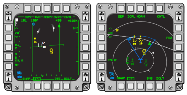
Datalink uses UHF and VHF radio to provide digital data communications with other users that have an IDM (Improved Data Modem). The IDM converts digital data to audio data for UHF or VHF radio transmission. When data is received from other users, the IDM converts the audio data to digital data and sends it to the avionics system for display in the cockpit.
Datalink must not be confused with the link 16.
Contents
Learning objectives
- Understand how to pre-brief IDM
- Host a datalink session
- Enter IDM information in the DED
- Understand cursor data vs. mark point data
- Recognize HSD symbology for datalink
Learning Files
Video from Krause made with BMS 4.32
General information
Introduction
Datalink allows the flight lead and his wingmen increased situational awareness (SA), the ability to pass positional information about each jet in the flight to all flight members, to target flight members on to air-to-air or air-to-ground targets, to easily execute tactics that go beyond the visual arena and regain visual mutual support should a flight member become a “lost wingman”.
The DL system allows up to 8 IDM equipped aircraft to transmit and receive intraflight data link messages.
Modes of operations
Demand Mode Operation
The Demand (DMD) and Assign (ASGN) data link modes allow a team member to obtain a “one-shot” team situational awareness update (an intraflight transmission round) on an “as needed” basis.
The DMD and ASGN modes also enable the option to make assignments to other flight members.
The messages transmitted allow each member to see the positions and headings of other members and their bugged target on the HSD page and FCR page
Beware : Both A-A Request and A-A Reply messages are snapshots in time. Reply messages are extrapolated for 8 seconds. Once this extrapolation period ends, the symbols will disappear.
Continuous Mode Operation
The Continuous (CONT) mode allows the pilot to request continuous update of request and reply intraflight messages. This is the mode that also requires coordination amongst flight members if you are flying in the multiplayer environment, as only one aircraft needs to be in CONT mode and initiates the CONT data link round.
Data Link Symbology
Air-to-air and air-to-ground data link information may be selected for display on the HSD MFD format by selecting ADLINK (OSB 16) and/or GDLINK (OSB 17) on the HSD CNTL page (both are on by default).
When ADLINK is selected, intraflight member’s ownship positions and the locations of their bugged targets are displayed on the HSD. This same symbology is also displayed on the FCR provided the FCR is in one of the air-to-air radar modes.
When GDLINK is selected, data linked steerpoint (or mark-point) and FCR air-to-ground cursor positions will be displayed on the HSD.
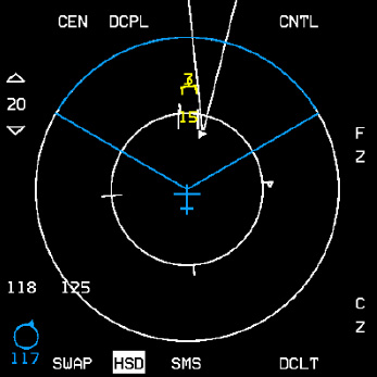
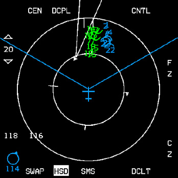
- Data Link Friendly: Wingmen are displayed on the HSD by a half circle with a line projecting from the top of the half circle. The symbols are oriented on the HSD based on ground track. Flight member number is displayed at the top of the symbol and altitude is displayed at the bottom of the symbol.
- Data Link Unknown: Ownship and wingmen's bugged targets are depicted as half squares with a line projecting from the top half of the half square. Flight member assignment number and target altitude are displayed at the top and bottom of the symbol, respectively.
- Data Link Targets: Outside the HSD FOV. Data link friendly or data link unknown targets which are outside of the HSD field-of-view are indicated by an arrow pointing in the direction of the target positioned on the outer range ring of the HSD.
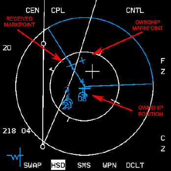
- Data Link Steerpoints: Are stored in steerpoints 71-80. Ownship Markpoints are shown as a small X symbol. Data link steerpoints are shown as a large X.
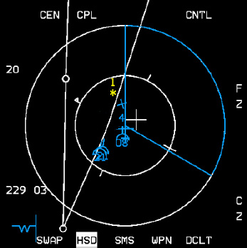
- Data Link FCR A-G Cursor Position: The data link A-G cursor position is displayed on the HSD as an asterisk with the sending flight member's number above it.
Important notes for fraggers and Package/Flight leaders
During mission planning/ mission building, when you are building a package of aircraft, the first flight (in this case a 4-ship) in a package will be assigned addresses 11-14. The next flight will be 21-24 and so on.
If during planning you adjust takeoff times so that, for example, the first flight you created takes off later than another flight in the package, the first flight you created will still use addresses 11-14.
This is important because your IDM addresses may be different than what you thought they were going to be.
If you were not familiar with the order in which the flights within the package were created. A good technique is to check the order of the flights in your package on the Briefing page in UI before you commit to 3D.
It will list them in order. This can help you select the right transmit addresses for other flight in your package (if there are several flights in the package and you want to monitor the location of any of those flights).
IDM Cockpit (DED) Initialization
In order to effectively exchange information, each participating data link user must have compatible parameters initialized into his respective IDM terminal. In BMS, initialization parameters are automatically fed into the IDM – to an extent. Ownship team address numbers and other flight member team addresses are done for you. These addresses are for your (up to 4) intraflight members.
The additional team addresses 5-8 are not filled in and must be keyed in manually, based on the pilot’s needs or a package commander’s needs.
For example, you are 2-ship of DCA and the first flight of a package that has 4 flights in total. You are addresses 11-12; already in the left column. You decide that you want to maintain situational awareness primarily on the flight leads of the other flights. You can enter 21, 31, and 41 in the IDM and receive their positions on the HSD, or you can enter 2 of those addresses in the left column and also receive information on any radar contacts they lock up.
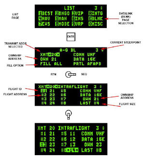
As seen in the picture on the right, LIST → ENTR gets the pilot to the A-G DL page.
The only two selectable options in this page are the Transmit Address (XMT) and the FILL option.
The FILL option determines whether the system stores (ALL) or ignores (NONE) all received data link steerpoints (71-80).
- When ALL is selected (default), the system will store the first message in STPT 71 and fill each subsequent STPT until it hits 80, upon which it will wrap around to the oldest location (71) and overwrite the data.
- When NONE is selected, no HUD or VMU (Voice Message Unit) messages are provided for these messages.
In most cases, FILL ALL is used. The FILL option has no impact on A-A intraflight or A-G cursor messages – they will be processed normally.
Sequencing right (SEQ) changes to the INTRAFLIGHT page, where up to 7 team addresses can be reviewed and changed (ownship address cannot be changed in BMS).
Hosting data
- Assign IDM in briefing like AA tacan assignments
- designate DL back-up flight (in case of flight leader being shot down)
- 1 player in CONT mode to host the flight datalink
- All other players in DMD mode
- COMM Switch Left - IFF Out LONG to start hosting data link
Air-To-Air Intraflight Data Link
The following applies to making a data link A-A assignment:
- Ensure the system currently has a FCR TOI (target of interest).
- Depress the OSB (7 through 10) adjacent to the ID associated with the assignee team member (1, 2, 3, or 4); verify assignment ID is replaced by highlighted “XMT” mnemonic for 2 seconds.
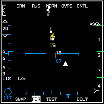
- Verify display of the team member ID above the FCR target symbol on the FCR page. The ID is displayed until the FCR track is no longer valid or a different target is assigned to the same team member.
The following applies to assignment operation for receiving aircraft.
Reception of an assignment message is independent of data link mode. The following process describes the reception of an assignment message:
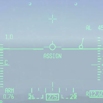
- Upon reception (indicated by the tone in the headset), verify display of “ASSIGN” in the upper middle part of the HUD. The ASSIGN cue is displayed for 8 seconds or until depression of WARN RESET on the ICP.
- Verify VMU (a.k.a., Bitchin’ Betty) message “DATA” in the headset if ownship was the assignee.
- Verify display of data link assignment symbol on the FCR and HSD pages.
Following screenshot are showing FCR, HSD and HUD of an Assignee (element lead in this example)
Air-To-Ground Intraflight Data Link
The A-G intraflight data link function allows the transmission of data associated with the currently selected steerpoint or the A-G radar cursor position which can then be used by flight members to “walk” their sensors (A-G radar cursors, TGP, etc.) onto a target or point of interest.
Special Considerations for A-G DL Operation
The transmit address may be changed before transmitting a STPT or A-G cursor position. The system default is your team’s broadcast address (a number ending in “0”, i.e., 20 if you are the second flight in a package).
Transmitting to this broadcast address will send the data to individual groups or teams with the same first digit in their ownship address: e.g., transmit address 20 will transmit to addresses 21-24.
- For example, the flight leader of four F-16s wants to data link a markpoint to all members of his flight and their addresses are 21 through 24, he would enter a transmit address of 20 in the XMT field and initiate data link transmission with SimCommsSwitchRight (Page Down). The data linked mark point would be displayed on the HSDs of all flight members in the intraflight link. Likewise, if his 4-ship is a part of a package of 8 aircraft and the other flight’s broadcast address was 10, he could enter 10 and transmit A-G data to the other flight of four.
A transmit address not ending in zero is directed to a single respective aircraft.
- For example, if a pilot wanted to send a mark point to only his #3 wingman, and the wingman's team address is 23, the pilot would have to enter 23 (the wingman’s address) in the transmit address field on the AG Data Link page. When the pilot transmits the message only wingman #3 will receive the message and have the markpoint displayed on his HSD.
Entering in a specific transmit address is only for A-G operations and does not affect A-A intraflight data link.
Transmission of data to a single aircraft can be done to a member outside of your immediate 4-ship team. In other words, if you were address 21 and there was a flight of 4 with addresses 11-14 and you wanted to transmit a mark point to only the leader of that flight, you would enter 11 as the transmit address and initiate the data link transmission as above.
Datalink selected steerpoint
A-G steerpoint data link is accomplished hands-on using the HSD as SOI.
- The HSD must be selected as the SOI (if not use the DMS (Display Management Switch) aft position, upon which the MFD SOI (Sensor of Interest) box (around the MFD perimeter) is placed on the HSD).
- Hands-on selection of the steerpoint location is done by placing the HSD cursor on the desired steerpoint and designating with TMS forward.
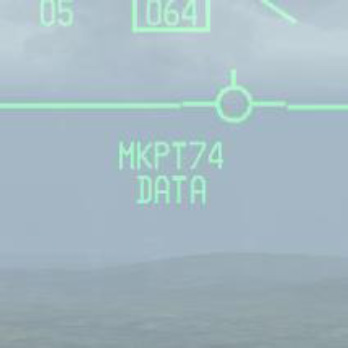
- Transmission of the A-G data link message is accomplished by depressing the Comms switch right while the HSD is SOI and also triggers an audible tone in the headset. A highlighted XMT will also be displayed adjacent to OSB 6 on the HSD base page.
Alternatively, the pilot may select the steerpoint he wants to data link via the UFC (Up-Front Controls – ICP), switch the SOI to the HSD and then depress Comms switch right. Data link steerpoints shows up as a large X symbol on the HSD and are stored in steerpoints 71-80, which allows multiple DL steerpoints to be retained by the navigation system. Once they are all filled up, #71 will be overwritten and subsequent DL STPTs will overwrite the other numbers.
Datalink FCR Cursor Position
Transmitting A-G cursor position
The A-G cursor function provides a hands-on transmission of A-G FCR cursor position. This function is available independent of system master mode while the FCR is in ground map (GM), ground moving target (GMT), or SEA modes and requires the FCR to be the sensor of interest (SOI) for transmission. It also provides A-G cursor data link reception independent of any data link mode.
Transmitting ownship A-G cursor coordinates is accomplished hands-on by making the FCR the SOI.
- Slew the radar cursor with the CURSOR/ENABLE control to the point-of-interest
- depress COMM switch right on the throttle
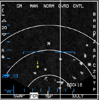
An audio tone is audible in the headset and the mnemonic XMT is highlighted for two seconds adjacent to OSB 6 on the HSD. The pilot will not see his own A-G cursor position data link symbol, which is a yellow asterisk (*) symbol (see Figure below).
Receiving A-G cursor position
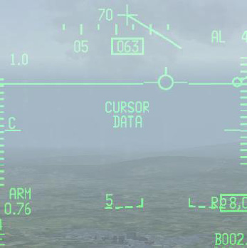
Reception of A-G cursor data link message is independent of the current data link mode. Several cues are provided by the avionics system to indicate reception of a data link message. An audio tone is activated followed by the aural VMU message “DATA” in the headset and the HUD message, “CURSOR” and “DATA” in the middle of HUD.
This HUD message remains until the DRIFT C/O switch is positioned to WARN RESET on the ICP or the data is no longer valid (i.e. 13 seconds has elapsed since cursor reception).
After reception of an A-G cursor message, the HSD and/or FCR (if it is in one of the three ground-map modes – GM, GMT, SEA) displays the data linked A-G cursor symbol (*).
The symbol is displayed with an ID (1-4) which represents the message source (team member 1-4), or displayed as a 2-digit number representing the IDM address of another member of the 8-ship team that is not members 1-4).
This symbol remains on screen for a total of 13 seconds and begins flashing during the last 5 seconds if it is within the display FOV.
Important notes :
- This symbol is blanked on the FCR if either FZ is selected, or the radar is in FTT (fixed target track).
- No A-G cursor symbol will be displayed on the HSD if ground data link has been decluttered (via OSB 17) on the HSD control page.
- The system stores and displays a maximum of 3 different data linked cursor positions simultaneously; subsequent receptions overwrite existing locations in a rotary fashion. The data linked cursor position is not stored in a steerpoint.
Useful controls
| CONTROLS | ACTION |
|---|---|
| TQS: COMMS Switch Left - IFF OUT | Initiates A/A datalink (if held 1/2 sec or more) - Declutter FCR datalink symbols (if held less than 1/2 sec) The display will remain decluttered until Comms switch is toggled again for less than 1/2 sec. |
| TQS: COMMS Switch Right - IFF IN | Datalink AG FCR cursor position if FCR is SOI - Datalink currently selected groundpoint is HSD is SOI (steerpoint, markpoint etc ...) |
| DRIFT C/O switch (WARN RESET) | The lower momentary position is labelled WARN RESET and is used to reset the HUD message. |
{{#invoke:Navbox|navbox}}
