Difference between revisions of "Air-to-ground TGP"
| (3 intermediate revisions by 2 users not shown) | |||
| Line 13: | Line 13: | ||
# Know how to use the IR pointer (PTR) to guide friendly aircraft on a target during flight with NVGs | # Know how to use the IR pointer (PTR) to guide friendly aircraft on a target during flight with NVGs | ||
<br /> | <br /> | ||
| + | =Introduction= | ||
| + | The AN/AAQ-33 Sniper Extended Range (XR) ATP is an electro-optical targeting system in a single, lightweight pod that is compatible with the latest precision-guided weapons for detecting, identifying and engaging multiple moving and fixed targets in air-to-air and air-to-ground engagements.<br/> | ||
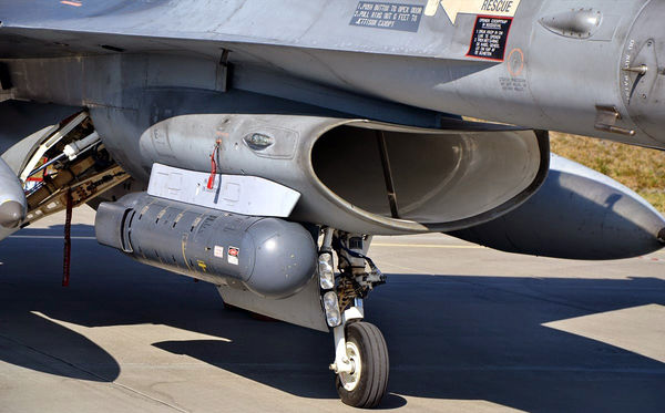
| + | The Sniper XR ATP installs under the engine inlet on the right side of the aircraft as with previous targeting pods, yet is considerably narrower in diameter and lighter in weight, offering corresponding drag benefits.<br/> | ||
| + | =TGP Symbology= | ||
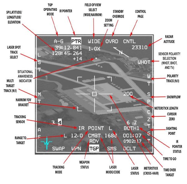
| + | [[File:TGPsymbol.jpg|none|600px]]<br/> | ||
| + | =Operating mode / Menu page= | ||
| + | *OSB 1 displays the current operating mode and accesses the Mode Menu page. | ||
| + | *Operating mode selection is Master mode dependent; for the A-G Master mode, the TGP maybe in A-G or STBY.<br/> | ||
| + | =Sensors= | ||
| + | There are 2 different types of sensors in the Sniper TGP. They both have settings and zoom that can be adjusted. | ||
| + | ==Flir sensor== | ||
| + | The FLIR sensor detects relative temperature differences between an object and its surroundings and displays them, roll-stabilized, as different shades of grey on the MFD TGP page.<br/> | ||
| + | The FLIR video can show white objects as hot (WHOT) or black objects as hot (BHOT). Polarity can be changed by pressing OSB 6 hands off or by TMS-left on the HOTAS (with TGP as SOI).<br/> | ||
| + | ==TV sensor== | ||
| + | The TV sensor can be selected by pressing OSB 6 or by clicking TMS-Left twice in less than 0.5 seconds. The TV has only 1 FOV 0.5° x 0.5° and one polarity, so TMS-Left will not change anything in this mode.<br/> | ||
| + | ==Field of View== | ||
| + | *The Sniper has 2 FOVs for the FLIR sensor: Wide and Narrow. The FOV can be switched between WIDE and NARO via OSB 3 or with the Expand/FOV switch (Pinky) on the HOTAS. | ||
| + | *The TV has only 1 FOV 0.5° x 0.5°<br/> | ||
| + | ==Variable Zoom== | ||
| + | *The Sniper provides electronic zoom control that can be changed from 1x to 4x using the MAN RANGE/UNCAGE knob on the HOTAS. | ||
| + | *The variable zoom stays the same between sensor changes and the variable zoom setting label appears below the FOV label under OSB 3.<br/> | ||
| + | ==North pointer== | ||
| + | is located in the top right of the TGP screen and shows an arrow pointing north.<br/> | ||
| + | |||
| + | =Laser designator= | ||
| + | The Sniper XR ATP provides a laser transmitter and receiver operating at both combat and eye-safe wavelengths. The laser is used for ranging for navigation updates, for mark points, designating for some weapons and for LGB delivery.<br/> | ||
| + | |||
| + | ==Laser setup and LGB employment== | ||
| + | Laser setup and use for LGBs has been covered in the [[Laser guided bombs]] section.<br/> | ||
| + | ''Note: This applies to all CCRP bomb drops; hold the pickle button for a few seconds before the release cue''.<br/> | ||
| + | |||
| + | ==Laser ranging== | ||
| + | *When the laser is firing and the laser beam can reach the SPI position (laser is valid) an L will replace the T on the TGP MFD page next to the range in the lower left corner. | ||
| + | *When laser ranging happens then the range to SPI (slant range) information in the lower right of the HUD will be preceded by an L as well.<br/> | ||
| + | =IR pointer= | ||
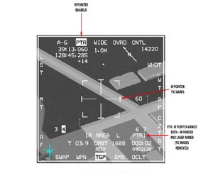
| + | [[File:irpointer.jpg|thumb|TGP IR pointer symbology]] | ||
| + | ==Basics== | ||
| + | The Sniper can fire an IR Pointer beam that can be detected by NVGs. IR pointer status can be selected by pressing OSB 2 on the MFD or by 2x TMS-Right < 0.5 seconds.<br/> | ||
| + | ==Use of IR pointer with laser designator== | ||
| + | *When the IR pointer is selected, the PTR label under OSB 2 will be highlighted and a number 1-4 will show up in the lower right corner next to PTR. | ||
| + | *The number 1-4 indicates the flash pattern that the PTR is using; this way it's possible to distinguish between 4 different IR pointers being fired at the same time.<br/> | ||
| + | ==Switching between IR Pointer and laser== | ||
| + | The IR Pointer is fired by pressing the trigger detent to either position. When the IR Pointer is fired, the PTR or BOTH labels under OSB 2 and in the lower right corner of the MFD will flash. If BOTH mode is selected the IR Pointer and laser can be fired simultaneously.<br/> | ||
| + | The option for the IR pointer are: | ||
| + | #Disabled - PTR OSB not flashing | ||
| + | #Enabled - PTR OSB flashing | ||
| + | #Both - BOTH on the PTR OSB<br/> | ||
| + | |||
| + | =TGP A-G Submodes= | ||
| + | There are multiple submodes in which the TGP operates. They are noted below. | ||
| + | ==Slave Submode== | ||
| + | In slave submode the Sniper follows the System Point Of Interest (SPI) position. In A-G mode the SPI position is determined by the current sensor that controls the SPI - usually the steerpoint until TGP is put into a track mode.<br/> | ||
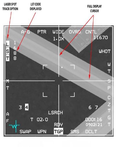
| + | ==LST== | ||
| + | *The LST can detect and track laser spots being designated by other aircraft in BMS. | ||
| + | *The LST detection FOV is 3° | ||
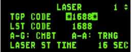
| + | *The code of the fired laser '''must match the LST code''' that is set on the DED Laser page. | ||
| + | *When using the LST the laser and IR pointer cannot fire. | ||
| + | *The pilot can select LST mode hands off by pressing the MAN RNG/UNCAGE knob | ||
| + | [[File:DEDlaser.jpg|thumb|Laser codes on the DED page]] | ||
| + | [[File:LSTsym.jpg|thumb|400px|LST symbology]] | ||
| + | |||
| + | *When the LST function is started, the pod starts a search for a laser illuminated spot inside a 3° FOV around the SPI position. | ||
| + | *When a laser spot with laser code that matches the LST laser code is detected the Sniper tracks the spot and a small tracking box is displayed at the crosshairs. | ||
| + | *LST mode is exited when the pilot commands AREA or POINT track, enters slave mode with TMS-Aft, or by pressing the MAN RNG/UNCAGE knob or OSB 20. | ||
| + | |||
| + | There are two modes in which LST operates and they are displayed at the bottom of the HUD: | ||
| + | #LSRCH indicating LST search | ||
| + | #DETECT for LST detection of laser energy prior to full track | ||
| + | #LTRACK for LST track<br/> | ||
| + | |||
| + | ''Note: The SPI position and the LST tracked spot position may not coincide. The pilot should command AREA or POINT track before dropping ordnance on the SPI.''<br/> | ||
| + | |||
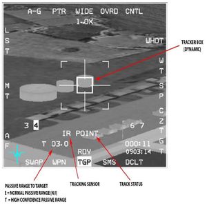
| + | ==Point Track== | ||
| + | [[File:TGPpoint.jpg|thumb|TGP symbology in point track.]] | ||
| + | *POINT track mode tracks single objects with well-defined edges, e.g. vehicles, some buildings. When POINT Track is established a box grows from the center of the crosshairs until the edges of the target are enclosed by it. | ||
| + | *POINT is displayed below the crosshairs, indicating that track has been established. Designating with TMS-up and hold, with TGP SOI, commands AREA track to ground-stabilize the LOS. POINT Track is commanded by releasing TMS-up. | ||
| + | *If the TGP cannot maintain POINT track because LOS to the target is blocked (pod masked or target hidden behind another object for example) then the pod will drop POINT track and switch to INR or AREA track until the pilot commands POINT track again on the target. | ||
| + | *TMS-aft commands the TGP to break track and return to the SLAVE mode, meaning it is slaved back to the radar LOS. | ||
| + | |||
| + | ==Area Track== | ||
| + | *AREA track can track areas which aren't capable of being point tracked | ||
| + | *AREA track is often commanded first in order to help stabilize the TGP display before you find a specific target to be POINT tracked. | ||
| + | *AREA track is commanded by TMS-Right on the side stick controller when TGP is SOI. The pod will also enter AREA track with TMS-Up and hold (releasing TMS-Up will enter POINT track) if the pod is in A-G mode. | ||
| + | |||
| + | ==Inertial rates (INR)== | ||
| + | The explanation for the INR submode can be found under the [[Air-to-air TGP]] section | ||
| + | |||
| + | =AGM-65D handoff= | ||
| + | The explanation for this can be found under the [[Mavericks]] section. | ||
| + | |||
| + | =TGP Frag radius= | ||
| + | Note: All the cluster munitions have been set with a BA of 2500ft and the frag radius has a rectangular shape with the longest side facing the flying direction at the moment of the drop | ||
| + | |||
| + | {| class="wikitable" | ||
| + | |- | ||
| + | !Bomb type | ||
| + | !Blast radius | ||
| + | |- | ||
| + | |Mk 20 | ||
| + | |410ft | ||
| + | |- | ||
| + | |Mk 82 | ||
| + | |410ft | ||
| + | |- | ||
| + | |Mk 84 | ||
| + | |710ft | ||
| + | |- | ||
| + | |CBU-58 | ||
| + | |450x600ft | ||
| + | |- | ||
| + | |CBU-59 | ||
| + | |450x600ft | ||
| + | |- | ||
| + | |CBU-71 | ||
| + | |410x600ft | ||
| + | |- | ||
| + | |CBU-87 | ||
| + | |450x800ft | ||
| + | |- | ||
| + | |CBU-97 | ||
| + | |500x1200ft | ||
| + | |- | ||
| + | |CBU-103 | ||
| + | |410x600ft | ||
| + | |- | ||
| + | |CBU-105 | ||
| + | |410x600ft | ||
| + | |- | ||
| + | |GBU-10 | ||
| + | |710ft | ||
| + | |- | ||
| + | |GBU-12 | ||
| + | |310ft | ||
| + | |- | ||
| + | |GBU-24 | ||
| + | |710ft | ||
| + | |- | ||
| + | |GBU-31 | ||
| + | |710ft | ||
| + | |- | ||
| + | |GBU-39 | ||
| + | |310ft | ||
| + | |- | ||
| + | |AGM-154C | ||
| + | |710x800 ft | ||
| + | |- | ||
| + | |} | ||
| + | |||
| + | |||
=Keybinds and functions= | =Keybinds and functions= | ||
{| class="wikitable" | {| class="wikitable" | ||
| Line 47: | Line 196: | ||
|- | |- | ||
|} | |} | ||
| + | |||
| + | {{Nav UOAF}} | ||
[[Category:UOAF]] | [[Category:UOAF]] | ||
[[Category:UOAF: BMS Codex]] | [[Category:UOAF: BMS Codex]] | ||
Latest revision as of 15:20, 12 February 2018
In falcon BMS, the F16 can carry either a Lantirn or a Sniper XR designation pod depending on the block. Those targeting pods (TGP) provides positive target identification, autonomous tracking, GPS coordinate generation, and precise weapons guidance from extended standoff ranges.
In the air to ground task, they're mainly used to guide LGB on their targets. They also are equiped with a boresight correlator for automatic lock-on of the AGM-65 Maverick imaging infrared missiles.
Contents
Learning objectives
- Set up the Laser page in the DED (combat mode, codes and lasing timer)
- Know the basic symbology of the TGP page
- Know how to switch between different camera modes (WHOT - BHOT - TV) and how to zoom
- Understand what is the airframe masking and how to use the situational awareness indicator to avoid it.
- Know the usefull functions of the HOTAS concerning TGP (pinky switch for FOV, TMS left for TGP polarity etc)
- know the different methods of lasing (Timer or manual with first trigger detent)
- Know how to use the laser spot tracker (LST)
- Know how to use the IR pointer (PTR) to guide friendly aircraft on a target during flight with NVGs
Introduction
The AN/AAQ-33 Sniper Extended Range (XR) ATP is an electro-optical targeting system in a single, lightweight pod that is compatible with the latest precision-guided weapons for detecting, identifying and engaging multiple moving and fixed targets in air-to-air and air-to-ground engagements.
The Sniper XR ATP installs under the engine inlet on the right side of the aircraft as with previous targeting pods, yet is considerably narrower in diameter and lighter in weight, offering corresponding drag benefits.
TGP Symbology
Operating mode / Menu page
- OSB 1 displays the current operating mode and accesses the Mode Menu page.
- Operating mode selection is Master mode dependent; for the A-G Master mode, the TGP maybe in A-G or STBY.
Sensors
There are 2 different types of sensors in the Sniper TGP. They both have settings and zoom that can be adjusted.
Flir sensor
The FLIR sensor detects relative temperature differences between an object and its surroundings and displays them, roll-stabilized, as different shades of grey on the MFD TGP page.
The FLIR video can show white objects as hot (WHOT) or black objects as hot (BHOT). Polarity can be changed by pressing OSB 6 hands off or by TMS-left on the HOTAS (with TGP as SOI).
TV sensor
The TV sensor can be selected by pressing OSB 6 or by clicking TMS-Left twice in less than 0.5 seconds. The TV has only 1 FOV 0.5° x 0.5° and one polarity, so TMS-Left will not change anything in this mode.
Field of View
- The Sniper has 2 FOVs for the FLIR sensor: Wide and Narrow. The FOV can be switched between WIDE and NARO via OSB 3 or with the Expand/FOV switch (Pinky) on the HOTAS.
- The TV has only 1 FOV 0.5° x 0.5°
Variable Zoom
- The Sniper provides electronic zoom control that can be changed from 1x to 4x using the MAN RANGE/UNCAGE knob on the HOTAS.
- The variable zoom stays the same between sensor changes and the variable zoom setting label appears below the FOV label under OSB 3.
North pointer
is located in the top right of the TGP screen and shows an arrow pointing north.
Laser designator
The Sniper XR ATP provides a laser transmitter and receiver operating at both combat and eye-safe wavelengths. The laser is used for ranging for navigation updates, for mark points, designating for some weapons and for LGB delivery.
Laser setup and LGB employment
Laser setup and use for LGBs has been covered in the Laser guided bombs section.
Note: This applies to all CCRP bomb drops; hold the pickle button for a few seconds before the release cue.
Laser ranging
- When the laser is firing and the laser beam can reach the SPI position (laser is valid) an L will replace the T on the TGP MFD page next to the range in the lower left corner.
- When laser ranging happens then the range to SPI (slant range) information in the lower right of the HUD will be preceded by an L as well.
IR pointer
Basics
The Sniper can fire an IR Pointer beam that can be detected by NVGs. IR pointer status can be selected by pressing OSB 2 on the MFD or by 2x TMS-Right < 0.5 seconds.
Use of IR pointer with laser designator
- When the IR pointer is selected, the PTR label under OSB 2 will be highlighted and a number 1-4 will show up in the lower right corner next to PTR.
- The number 1-4 indicates the flash pattern that the PTR is using; this way it's possible to distinguish between 4 different IR pointers being fired at the same time.
Switching between IR Pointer and laser
The IR Pointer is fired by pressing the trigger detent to either position. When the IR Pointer is fired, the PTR or BOTH labels under OSB 2 and in the lower right corner of the MFD will flash. If BOTH mode is selected the IR Pointer and laser can be fired simultaneously.
The option for the IR pointer are:
- Disabled - PTR OSB not flashing
- Enabled - PTR OSB flashing
- Both - BOTH on the PTR OSB
TGP A-G Submodes
There are multiple submodes in which the TGP operates. They are noted below.
Slave Submode
In slave submode the Sniper follows the System Point Of Interest (SPI) position. In A-G mode the SPI position is determined by the current sensor that controls the SPI - usually the steerpoint until TGP is put into a track mode.
LST
- The LST can detect and track laser spots being designated by other aircraft in BMS.
- The LST detection FOV is 3°
- The code of the fired laser must match the LST code that is set on the DED Laser page.
- When using the LST the laser and IR pointer cannot fire.
- The pilot can select LST mode hands off by pressing the MAN RNG/UNCAGE knob
- When the LST function is started, the pod starts a search for a laser illuminated spot inside a 3° FOV around the SPI position.
- When a laser spot with laser code that matches the LST laser code is detected the Sniper tracks the spot and a small tracking box is displayed at the crosshairs.
- LST mode is exited when the pilot commands AREA or POINT track, enters slave mode with TMS-Aft, or by pressing the MAN RNG/UNCAGE knob or OSB 20.
There are two modes in which LST operates and they are displayed at the bottom of the HUD:
- LSRCH indicating LST search
- DETECT for LST detection of laser energy prior to full track
- LTRACK for LST track
Note: The SPI position and the LST tracked spot position may not coincide. The pilot should command AREA or POINT track before dropping ordnance on the SPI.
Point Track
- POINT track mode tracks single objects with well-defined edges, e.g. vehicles, some buildings. When POINT Track is established a box grows from the center of the crosshairs until the edges of the target are enclosed by it.
- POINT is displayed below the crosshairs, indicating that track has been established. Designating with TMS-up and hold, with TGP SOI, commands AREA track to ground-stabilize the LOS. POINT Track is commanded by releasing TMS-up.
- If the TGP cannot maintain POINT track because LOS to the target is blocked (pod masked or target hidden behind another object for example) then the pod will drop POINT track and switch to INR or AREA track until the pilot commands POINT track again on the target.
- TMS-aft commands the TGP to break track and return to the SLAVE mode, meaning it is slaved back to the radar LOS.
Area Track
- AREA track can track areas which aren't capable of being point tracked
- AREA track is often commanded first in order to help stabilize the TGP display before you find a specific target to be POINT tracked.
- AREA track is commanded by TMS-Right on the side stick controller when TGP is SOI. The pod will also enter AREA track with TMS-Up and hold (releasing TMS-Up will enter POINT track) if the pod is in A-G mode.
Inertial rates (INR)
The explanation for the INR submode can be found under the Air-to-air TGP section
AGM-65D handoff
The explanation for this can be found under the Mavericks section.
TGP Frag radius
Note: All the cluster munitions have been set with a BA of 2500ft and the frag radius has a rectangular shape with the longest side facing the flying direction at the moment of the drop
| Bomb type | Blast radius |
|---|---|
| Mk 20 | 410ft |
| Mk 82 | 410ft |
| Mk 84 | 710ft |
| CBU-58 | 450x600ft |
| CBU-59 | 450x600ft |
| CBU-71 | 410x600ft |
| CBU-87 | 450x800ft |
| CBU-97 | 500x1200ft |
| CBU-103 | 410x600ft |
| CBU-105 | 410x600ft |
| GBU-10 | 710ft |
| GBU-12 | 310ft |
| GBU-24 | 710ft |
| GBU-31 | 710ft |
| GBU-39 | 310ft |
| AGM-154C | 710x800 ft |
Keybinds and functions
| HOTAS | ACTION |
|---|---|
| Trigger first detent | Fire Laser or IR pointer or both |
| TMS UP | Commands POINT track on center of FOV |
| TMS Right | Commands AERA track on center of FOV |
| TMS LEFT | Toggle polarity (IR sensor only) |
| 2 x TMS LEFT < 0.5 sec | Switch between IR sensor and TV |
| TMS DOWN | Break track and return to slave mode |
| PINKY | Toggle FOV (wide - narrow) |
| MAN RNG (rotate) | Change variable zoom |
| UNCAGE | Toggle LST mode |
{{#invoke:Navbox|navbox}}
